Vehicle tyre size & the effect on ABS braking system
Applies to all ABS equipped vehicles
Some vehicles may exhibit unusual ABS system behaviour when the OEM tyers are replaced with ones that vary from the original size.
This behaviour can show up as excessive tyre chirping or erratic ABS system modulation during a panic stop. In severe cases the ABS warning light will illuminate, set a trouble code and disable the ABS control system.
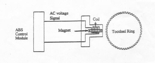
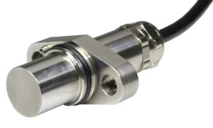
Replacement tyres should always be identical in size to the original tyres or be a factory recommended option for that vehicle. Tyre size and final drive ratio ( transaxle or differential ) detirmine the number of the teeth the manufacturer selects for the wheel speed sensor ring ( toothed ring ). The sensor ring is located on a number of different componenets such as front or rear rotor hub, rear axle flange, outer CV joint, tail shaft of the transmission or on the ring gear in the rear differential. These components rotate proportion to wheel speed. Wheel speed sensors are affixed to a stationary component near the sensor ring.ABS
The sensors work in conjunction with sensor rings, to produce an AC voltage signal. The ABS control module utilizes this signal to interpret the rotational speed of the tyre and wheel assembly. Deviating from the factory recommended tyre size affects the rotational speed of the sensor ring which in turn causes excessive variation in the voltage signal to the ABS controller. A tyre smaller than OE will generate a signal that causes the ABS control module to interpret that the vehicle is travelling at a higher rate of speed than it actually is. The opposite is true for a tyre that is larger than original equipment.
Bottom line, don’t install tyres that are of a different size and preferably replace worn tyres in matched sets of four.
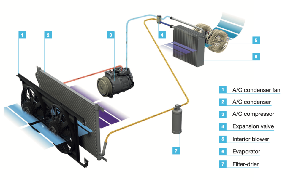
Before installing a new air conditioning compressor, always check the quantity and condition of the oil in the old compressor.
Always flush the refrigerant circuit
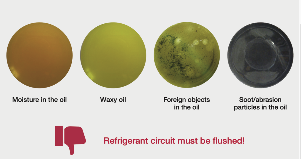
As a general rule, the refrigerant circuit must always be flushed if an air conditioning compressor has been damaged. This is the only way to prevent consequential damage caused by foreign objects, for example.
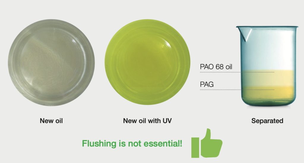
Flushing completely removes the old compressor oil from the system (compressors, filter-driers, expansion valves, and multi-flow condensers cannot be flushed). When refilling afterward, the new compressor is filled with the entire quantity of oil.
Replacement without flushing: always adjust the oil quantity
When replacing an air conditioning compressor, the flushing step can only be skipped in very exceptional cases, such as an electrical defect. However, it’s still essential to ensure that the system is clean, leaktight, and filled with the right quantity and specification of compressor oil.
If an air conditioning compressor is being replaced without flushing, it’s especially important to reduce the quantity of oil in the new compressor to avoid overfilling and potentially causing serious damage.
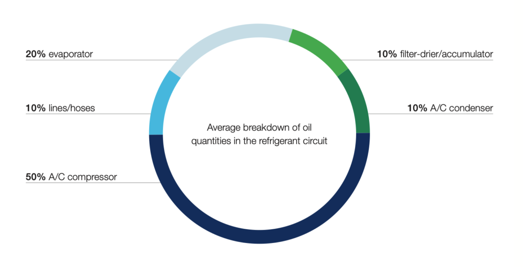
About 50% of the compressor oil is found in the compressor, while the rest is distributed among the system’s other components. If further components are replaced, their percentage share of the total quantity of oil (see pie chart) must be taken into account during filling.
Oil distribution in the air conditioning system
All MAHLE & NISSENS air conditioning compressors are filled with oil at the factory. To avoid overfilling the system, the oil from the new compressor must first be drained off into a clean container.
The oil from the defective compressor should be drained off into a second container and the quantity gauged using a measuring jug. The quantity of fresh oil that is added to the new compressor should correspond to the quantity of used oil. The oil from the old compressor should not be reused and must be disposed of in an environmentally friendly manner.
Important!
If the old compressor contained more than 50% of the system’s entire quantity of oil, it’s safe to assume that the system had been overfilled. If less than 30% of the entire oil quantity is found in the compressor, there’s probably a leak somewhere.
The quantity of oil drawn off when using an air conditioning service unit to evacuate the A/C system also needs to be added. In either case, flushing the refrigerant circuit to remove the old oil is vital. Only then can you be sure that the system contains the correct amount of oil after the repair.
For more technical information on compressor installation visit:
https://support.nissens.com/en/material/ac-compressor-installation-guide

Alfa Timing Belt Intervals
Recomended timing belt replacement intervals for a number of Alfa Romeo vehicles may differ from that originally printed in the owners handbook.
It is important to follow the latest manufacturers recommendation to ensure that no major engine damage occurs to vehicles you are responsible for servicing.
The recommended timing belt replacement service interval is 60,000km or three years, whichever occurs first, for the following Alfa Romeo models.
APPLICABLE MODELS
GT
GTV
SPIDER
166
156
147
APPLICABLE ENGINES
2.0L TWIN SPARK
2.0L JTS
2.5L V6
3.0L V6
3.2L V6
Bedding in your new brake pads
To gain long lasting life & performance from your brake pads, follow these 4 simple steps.
1. Accelerate the vehicle to 60km/h
2. Apply the brakes using moderate to firm pedal effort, reducing the speed of the vehicle to 10km/h (Do not come to a complete stop.)
3. Continue driving for 100m-200m accelerating back to 60km/h.
4. Repeat this process 6-10 times, allowing approximately 30 seconds of driving between stops for brake cooling.
(Do not come to a complete stop during the process to avoid uneven bed in.)
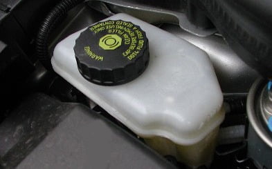
Replace your brake fluid
Replacing brake fluid can often be overlooked at regular service intervals. Unfortunately brake fluid is as vulnerable to degradation as any other lubricant or fluid in the vehicle more so when the vehicle is not being used.
Corrosion inhibitors and stabilisers in brake fluid deplete over time and need to be changed regularly.
These are ‘hygroscopic’, which means that any moisture within the braking system is absorbed throughout the entire system rather than collecting in spots. This reduces the chance of localised corrosion or boiling.
Moisture is drawn through the master cylinder cap as well as through the brake hoses.
In poorly serviced older vehicles it is not unusual to find fluid that has 7-8% water content. This moisture content slowly thickens the fluid, reduces its ability to flow and also decreases its ability to stop corrosion.
One of the most significant changes that increased moisture brings is a reduction in fluid boiling temperature. Brake fluid can commonly see 150-200’c at the brake callipers and a 2% water content can result in a 90’C drop in the boiling point. This combination of lower boiling point along with high temperatures can introduce vapour lock under adverse braking conditions, with potentially fatal results.
DOT3 specification brake fluid can reach its recommended service level of 175’C in as little as one year in service, while DOT4 specification brake fluid will reach this level after about two years.
While many manufacturers recommend a fluid change every two years, a prudent fluid change interval for these fluids would be every year for DOT3 and every two years for DOT4.
Rather than relying on time based intervals alone, it is also possible to test the boiling point of a fluid in your workshop with the correct testing equipment. This can either be a dedicated brake fluid refractometer or a tester that actually boils a test sample of the fluid to measure its boiling point.
Premature seal failure
The most common cause of premature seal failure is contamination of the fluid while servicing.
Swelling of the rubber seals occur because of the introduction of petroleum-based products such as engine oil, power steering fluid and other lubricants, even a small amount on a cleaning rag is enough to do damage. Contamination can also come from abrasive dirt or foreign material entering the reservoir when the cap is removed. The cap and surrounding area should be clean before removing the cap and make sure that the cap is clean and dry before refitting.
Storage and handling
Brake fluid should be stored in its original container in a clean and dry location away from heat. Once opened, replace the lid immediately after use, and use the entire contents as soon as possible. It is also important to tighten the lid on a 20 litre brake fluid container when not drawing out fluid. Many workshops now only buy smaller bottles of brake fluid to reduce moisture absorption in the workshop. Brake fluid is chemically similar to many paint solvents and therefore has a detrimental effect on automotive paints. If any spilled on paintwork wash it off immediately with water, do not wipe it off with a rag.
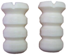
Bump Stops
Bump stops are a vital part of the suspension, they stop the shockers from over compressing.
If they are damaged or missing, the shocker will compress further than it’s rated travel point, which will cause damage to the internal valves, oil leaking from top seal, bending of the main shaft or in some cases complete failure of the shocker.
It is advised when replacing shockers, to also replace the bump stops as this will increase the life of the new shockers.
Running a vehicle without bump stops will greatly reduce the life of a shocker.
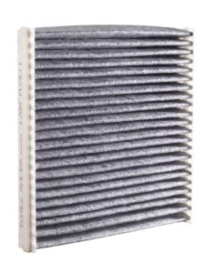
Why you should change your pollen filter
The range of cabin/pollen filters on the market is increasing due to the new knowledge of these filters. They are designed to extract out contaminates such as pollen, fungus spores, dirt, dust, soot and even exhaust gases. With these filters tucked away, a lot of the time there is no knowledge that they exist to the motorist or even some trade personal.
With the research that has been conducted on this product for over a number of years shows that there are more pollutants inside the cabin than outside (even up to 10 times higher in some cases).
The demand for this product is growing due to greater knowledge and known advantages for this product. It has taken off in Europe, America and now taking off in Australia with the number of new cars being fitted with this new ventilation system growing and growing each and every year.
It is reccomended that the pollen/cabin filter should be changed every 15,000 kilometers or at least once a year. With this filter incorporated in to a high percentage of all new cars sold, it means that motorist can relax about the health risks of pollutants inside the vehicle whilst travelling.
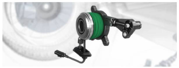
Concentric Slave Cylinders (CSC’s)
Many vehicles are now fitted with a concentric slave cylinder (CSC) as opposed to the conventional release fork and bearing: The conventional method of operation of the clutch is by cable or hydraulic actuation of a release fork, this disengages the clutch via a release bearing.
CSC release bearings enable a lighter clutch pedal effort with better take-up, allowing vehicle manufacturers to dispense of the release fork, guide and bearing.
The CSC is mounted inside the gearbox bell-housing and is usually made from either modern thermo-plastics or aluminium, with intricate rubber seals and chambers within.
When a clutch is replaced it is essential that the CSC is also replaced at the same time.
After many clutch actuations the rubber seals become worn and the operating position within the chamber of the CSC changes, which means the worn internal components are no longer aligned. It is imperative that the rubber seals inside CSCs are of the highest quality to ensure there is no loss of hydraulic fluid. If fluid is allowed to pass through the seals it will contaminate the friction material on the disc, which will result in clutch failure.
The CSC must not be compressed prior to fitment; this will damage the rubber seals as they are not fully lubricated.
What is the Difference between a DMF and SMF?
Most European Passenger and 4WD vehicles have a clutch system fitted with either a single mass flywheel (also known as a SMF) or a dual mass flywheel (also known as a DMF). These vehicles are fitted with different clutch kits respective of the flywheels that are fitted from the factory.
The dual mass flywheel was designed to help smooth out the torque produced by petrol and diesel engines, by increasing the kinetic energy stored on the input shaft side of the gearbox and provide easier gear changes and less drivetrain noise.
The single mass flywheel dampening springs are usually in the clutch plate. The dual mass design incorporates the dampening springs within the flywheel.
The main benefits of a single mass flywheel
-It is a cheaper alternative to replacing the DMF
-Increased durability due to no wearing parts in the flywheel
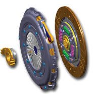
The images below show the visible difference between the dual mass and single mass flywheel.
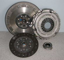
DMF – no springs are visible on the clutch plate (they are built into the flywheel)
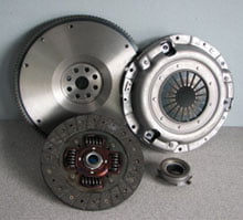
SMF – you can see the springs built into the clutch plate. Also evident is the difference in the flywheel (to the left at the back)
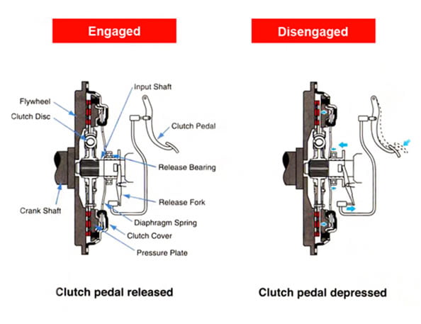
How Does A Clutch Work?
When the clutch pedal is pressed, a cable or hydraulic piston pushes on the release fork, which presses the throw-out bearing against the middle of the diaphragm spring. As the middle of the diaphragm spring is pushed in, a series of pins near the outside of the spring causes the spring to pull the pressure plate away from the clutch disc (see below). This releases the clutch from the spinning engine.
What is an oxygen sensor?
An oxygen sensor senses the amount of oxygen in the exhaust gas and sends a signal to the engine computer (ECM), which adjusts the air/fuel mixture to the optimal level.
Too much oxygen in the exhaust gases indicates a lean mixture, which can cause performance problems, including misfire. Too little oxygen indicates a rich mixture, which wastes fuel and results in excess emissions. Either condition can shorten the life of the expensive catalytic converter.
Not only are properly functioning oxygen sensors good for the enviroment, but they can save money in fuel costs, too. Replacing a worn-out oxygen sensor will do more than improve your vehicle’s performance and reduce harmful exhaust emissions. It can save hundreds of dollars a year in fuel costs.
When to replace an oxygen sensor?
The average oxygen sensor typically have a service life between 50,000kms and 100,000kms
Exposure to carbon, soot, harmful gases, anti-freeze, chemicals, thermal and physical shock will shorten the life of an oxygen sensor. This results in increased fuel consumption, poor engine performance and excessive exhaust emissions.
Pull Type Clutch, the Future of Clutch Actuation
An increasing number of new vehicles are being fitted with “pull type” clutches. With plenty of interest in the market place about the differences between the new pull type and the traditional “push type”.
Here is a summary of the differences and advantages.
The increasing torque output of modern engines has resulted in a requirement for clutches with higher clamp load. But because the clamp load is determined by the diaphragm spring, this means that a stiffer diaphragm is required to increase the clamp load. But of course the stiffer a spring is, the harder it is to bend, which means that the pedal effort is increased, resulting in what is called “heavy pedal”. And here is where is the problem occurs, because the tendency in modern cars is for greater comfort and less driver effort.
At this point please note that the words “pull” and “push” refer to the action on the diaphragm, not the method of moving the release lever.
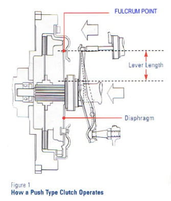
Simple physics and the law of levers tells us that the greater the lever length, the less the effort required to move a mass. A traditional push type clutch utilises only about 70-75% of the available diaphragm finger length to act on a fulcrum point and cause the release bearing to “push” the diaphragm spring, thereby removing the clamp load from the clutch.
See figure 1 for push type clutch operation.
In a pull type design the fulcrum point is relocated, by hinging the diaphragm under the lip of the cover and thereby lengthening the lever by up to 30%. The release bearing “pulls” the diaphragm to remove the clamp load from the clutch.
This means that for a given lever length, the pedal effort will be 30% less than an equivalent push type design. Therefore in a pull type clutch, for the same pedal effort as a push type clutch, the clamp load of the clutch can be increased by 30% without driver comfort.
Most older model cars like the peugeot 505 use a traditional push type clutch, most car models used this clutch up until the early 90’s then the clutch was changed to a pull type clutch for the increasing torque output of the modern engines.

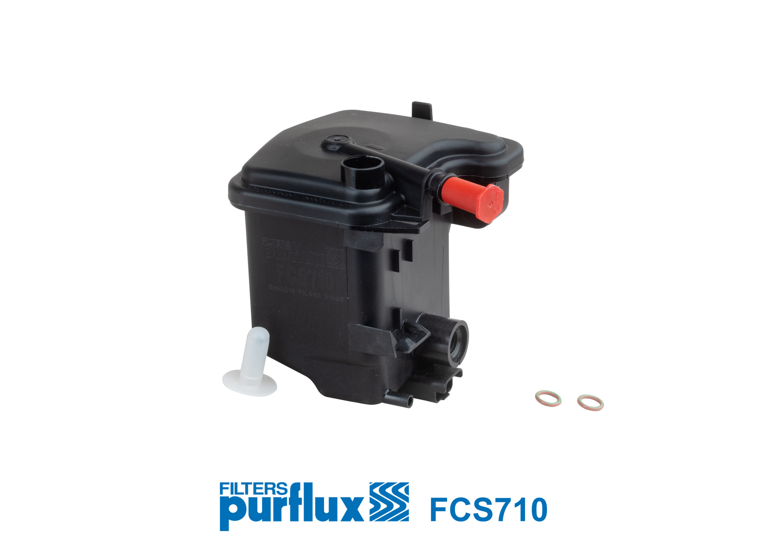
In the following link you will find fitting instructions for fuel filter 190195 (FCS710). This filter is equivalent to 3 different genuine numbers, 190167, 190181 & 190195. Models that have originally been fitted with 190195 have the water sensor switch included on the filter. The PDF below shows that as you screw in the temprature fitting, the flap is snapped off into the filter.
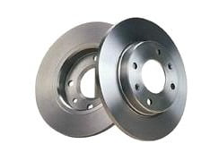
Rotor Minimum Thickness
Are you putting your customers and yourself at risk? There are still too many cars on the road with undersized rotors. In this article we highlight the importance of adhering to minimum thickness standards.
Definition: Rotor Minimum Thickness (RMT) is the minimum safe working thickness of a rotor beyond which it must be replaced.
Risk: Continued operation at RMT, or machining below RMT, means that safety can no longer be guaranteed and serious accident could occur. RMT is determined by the motor vehicle manufacturer during initial vehicle design. A number of criteria are used to determine RMT. Listed below are some of these criteria.
1. Heat absorption and dissipation
A brake system takes kinetic energy and transfers it into heat energy. Friction between the brake pads and the rotor generates heat which is then dissipated by convection to the atmosphere.
As a rotor reduces in thickness, its ability to absorb and dissipate heat generated during braking is reduced. Once RMT has been reached, the rotor’s ability to absorb and dissipate heat is reduced to such an extent, that a significant reduction in braking capacity can result.
This can be evident in premature fade and excessive stopping distance.
2. Caliper piston retention
As rotor thickness and brake pad thickness reduces, the caliper piston moves further out of the caliper body. RMT is established to allow sufficient piston supports in the caliper when combined with fully worn pads. If the rotor is less than RMT, then the piston may jam in the caliper bore causing possible brake lock or drag. Brake drag will lead to excessive heat build up and possible brake fluid vaporisation.
This will lead to half system failure and excessive stopping distance.
3. Brake pad retention
Fully worn brake pads and less than specified RMT can allow, in some applications for the pad backing plate to jam between the caliper bracket and rotor. This will either cause brake drag or wheel lock up. Both concerns can result in loss of vehicle stability.
4. Brake fluid retention
It is also possible under certain conditions when brake pads are fully worn & RMT is reached, that the caliper piston will no longer hydraulically seal. This will mean a leak and hydraulic failure to half the system.
False wheel speed sensor codes
Vehicles Involved: All vehicles equipped Anti-lock brakes.
When performing brake, suspension or drive train system diagnostics or service, it is possible to set a false diagnostic trouble code ( DTC ) if the wheel(s) are rotated with the ignition switched on. If a wheel speed sensor DTC is set, the system warming lamp will illuminate and the ABS computer will store the fault code.
NOTE: Warning lamp illumination signifies that the computer has detected a system malfunction and that the Anti-lock system is disabled. The ABS warning lamp will remain illuminated until the speed sensor code is cleared from computer memory. To clear a wheel speed sensor DTC from the ABS computer it may be necessary to use one of the following methods;
Cycle the ignition switch off and on, drive the vehicle over 25 km, ground the diagnostic test terminal in a particular sequence or use a scan tool. Refer to a current version of the manufacturer’s Anti-lock brake system service manual for the procedure on a specific vehicle.
Once the code has been cleared, the ABS warning lamp will remain off and the ABS is now operational. On some systems the DTC(s) may remain stored in the history portion of the ABS computer. These code(s) remain in computer memory until, either the vehicle has been driven a predetermined number of drive cycles or the vehicles ignition has been cycled a number of times.
On some systems a scan tool can be used to clear code(s) from history portion of the memory.
To eliminate the possibility of false wheel speed sensor codes during servicing, always ensure the ignition is in the off position prior to rotating the wheel(s).
Fitting a new radiator
(not the result of accident damage)
1. Before removing the radiator, check the system for stray current.
2. If no current leakage is found, flush out the existing coolant/inhibitor with a quality alkaline cooling system flush. Drain and rinse the cooling system, including the overflow bottle and heater core.
If stray current is found then refer to STRAY CURRENT CHECK PROCEDURE
IMPORTANT: Fit the new radiator and fill with water, re-check for any stray current.
3. Select the correct coolant/inhibitor which complies to Australian Standard AS2108-97 (A) and/or the vehicle manufacturers recommendations and fill the system using Distilled, Demineralized or Reverse Osmosis (RO) water to the correct ratios as recommended by the vehicle manufacturer. (This should be between 30-50% by volume).
Bring the engine up to temperature and let cool, re-check the coolant level and top up if necessary.
NOTE: Vehicle manufacturers instructions for filling the cooling system must be followed to ensure that air locks are removed from the cooling system.
Fitting a new radiator
(due to accident damage)
1. As the existing would be accident damaged, no initial stray current reading can be taken.
Fit the new radiator and flush the cooling system with a quality alkaline cooling system flush, drain and rinse the cooling system, including the overflow bottle, heater core and fill with water.
2. Check for stray current and if found the refer to STRAY CURRENT CHECK PROCEDURE.
3. If stray current is not present, or when the stray current problem has been corrected, drain the water from the cooling system.
4. Select the correct coolant/inhibitor which complies to the Australian Standard AS2108-97 (A) and/or the vehicle manufacturers recommendations and fill the system using Distilled, Demineralized or Reverse Osmosis (RO) water to the correct ratios as recommended by the vehicle manufacturers (this should be between 30-50% volume).
Bring the engine up to temperature and let cool, re-check the coolant level and top up if necessary.
NOTE: Vehicle manufacturers instructions for filling the cooling system must be followed to ensure that air locks are removed from the cooling system.